Electromaniacs
Would you like to react to this message? Create an account in a few clicks or log in to continue.
Electromaniacs

Where Imagination resonates with Innovation


You are not connected. Please login or register

CLONING ARDUINO

2 posters

Go down  Message [Page 1 of 1]

1CLONING ARDUINO Empty CLONING ARDUINO Mon Dec 22, 2014 9:46 pm

Admin


Admin

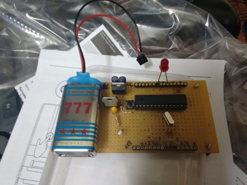
Hello guys. If you have great ideas in mind but the cost of arduino microcontrollers obstruct you! Well then you are in the right place now. Here we have some simple ways to clone arduino boards inexpensively and give you a small insight into the construction of arduino microcontroller boards. Pls note: we are not designing this procedure, but only giving you a compiled information found across the web.

https://electromaniacs.rpg-board.net

2CLONING ARDUINO Empty Re: CLONING ARDUINO Mon Dec 22, 2014 9:51 pm

Admin


Admin

Pls click the below link to construct a complete arduino uno board and you will be quite surprised after estimating its total making cost in contrast with the market cost.

Cloning an complete arduino uno board

https://electromaniacs.rpg-board.net

3CLONING ARDUINO Empty Re: CLONING ARDUINO Mon Dec 22, 2014 10:01 pm

Admin


Admin

https://electromaniacs.rpg-board.net

4CLONING ARDUINO Empty Re: CLONING ARDUINO Mon Dec 22, 2014 10:12 pm

Admin


Admin

A suggestion that would simplify the making further - "you could avoid including the USB serial converter into the chip to simplify the making". You could buy one arduino board and use it for programming all atmega328 microcontroller and then insert them into the clone for usage.
Any new atmega328 chip has to have a arduino bootloader file burned inside it to program it. You should use a avr InSystem Programmer(ISP) board to burn it. You could use a arduino UNO board itself as a ISP, which we'll be uploading shortly. You could also buy Pre bootloaded microcontrollers from ADAFRUIT website

https://electromaniacs.rpg-board.net

5CLONING ARDUINO Empty Re: CLONING ARDUINO Wed Dec 24, 2014 7:54 pm

pravin


Materials needed
-Dot board
-two 10 uf electrolytic capacitors
-two 10 uf tantalum capacitors
-7805 voltage regulator (5v)
-LM1117T-3.3 voltage regulator(3.3v)
-red LED
-two 150 ohm resistors
-10k resistor
-one 0.1 uf capacitor (ceramic disk)
-two 22 pf capacitors (ceramic disk)
-16 MHz crystal oscillator
-momentary push button switch
-jumper wires
-female headers
-female wall wart power jack
-ATmega328 with bootloader
-28 pin DIP IC socket

6CLONING ARDUINO Empty Re: CLONING ARDUINO Wed Dec 24, 2014 8:01 pm

pravin


Step 2: Install the socket

CLONING ARDUINO FHZHUDOH1YOHL3K.MEDIUM
CLONING ARDUINO F1FVSK6H1YOAPAD.MEDIUMCLONING ARDUINO FW2D6KJH1YOHL5G.MEDIUM
Picture of install the socket

The first step is after finding a good sized dot board
is to find a good place for the chip, and place the IC socket where you want it paying attention to the notch witch will be matched with the notch on the chip. also find where you want your power jack. You should place it on the edge of the board probably in the corner. I widened the holes on the board with a 1/16 inch drill bit, but still had to fold the leads on the jack using needle nosed pliers to get it to fit through. On the jack, the pin on the back connecting to the post on the inside is positive, and the one on the bottom connected to the metal on the inside is ground (the pin on the side is not needed. You could solder it for extra support, but I just broke it off). Remember this when connecting the regulators.

7CLONING ARDUINO Empty Re: CLONING ARDUINO Wed Dec 24, 2014 8:02 pm

pravin


Step 3: Adding the 5v regulator
CLONING ARDUINO FE1LFDEH1YOAOZM.MEDIUM

Picture of Adding the 5v regulator
Now it is time to add the five volt regulator. This is technically the only regulator you need to power the chip, but if you want a 3.3v pin (some breakout boards or sensors require 3.3v so the pin is nice to have), you will need to add the 3.3v regulator. These regulators require two decoupling capacitors each. Holding the 7805 printed side facing you, and the pins pointing down, the one furthest left is the input, the center is ground and the furthest right is the output. connect one 10 uf electrolytic capacitor to between the output and ground and the input and ground, being sure to connect the smaller leg to ground. connect the positive from the power jack to the furthest input pin, and ground from the power jack to the center pin.

8CLONING ARDUINO Empty Re: CLONING ARDUINO Wed Dec 24, 2014 8:03 pm

pravin


Step 4: Adding the 3.3v regulator

Picture of adding the 3.3v regulator
CLONING ARDUINO FQ2B231H1YOKA6M.MEDIUM
It is very important to remember that 3.3v regulator does not have the same pinout as the 7805. With the printed side towards you and the pins down the one furthest to the left is ground, the center is the output, and the furthest right is the input. Again you will need two decoupling capacitors. connect one of the 10 uf tantalum caps between output and ground and the other between input and ground paying attention to polarity. the positive lead should be labeled on the front of the cap, the other is negative, and be sure negative leads on these caps get connected to the furthest left pin on the regulator.

9CLONING ARDUINO Empty Re: CLONING ARDUINO Wed Dec 24, 2014 8:03 pm

pravin


Step 5: Indicator LED

Picture of indicator LED
CLONING ARDUINO FFSUYE9H1YOAP11.MEDIUM
Next you are going to connect the green LED to the output of the 7805 regulator to indicate when power is connected to the board. Connect the anode of the LED (longer leg) to the 150 ohm resistor, and then connect the resistor to the output pin of the 7805. connect the cathode (shorter leg, also indicated by being next to the flat side of the LED) to the center pin of the 7805. Once you do this it would be a good idea to plug it in to make sure you made all of the right connections. Once you are sure everything is right, you can move on.

10CLONING ARDUINO Empty Re: CLONING ARDUINO Wed Dec 24, 2014 8:05 pm

pravin


Step 6: Connecting power and ground pins

Picture of Connecting power and ground pins
CLONING ARDUINO F68S5ROH1ZG6FGH.MEDIUM
CLONING ARDUINO FISJ9GJH1ZG6FGI.MEDIUM
Now, you will begin making connections on the chip. connect pins 7, 20 and 21 to five volts and pins 8 and 22 to ground.

11CLONING ARDUINO Empty Re: CLONING ARDUINO Wed Dec 24, 2014 8:05 pm

pravin


Step 7: Reset button

Picture of Reset button
CLONING ARDUINO FJVOV5IH1YOHL4L.MEDIUM
On pin 1 (reset pin) connect the 10k resistor from the pin to 5v. Then connect one contact on the momentary push button switch to pin 1, and the other contact to ground.

12CLONING ARDUINO Empty Re: CLONING ARDUINO Wed Dec 24, 2014 8:06 pm

pravin


Step 8: Adding the crystal oscillator

Picture of Adding the crystal oscillator
CLONING ARDUINO FRZ24RNH1YOAP2Y.MEDIUM
solder the 16 MHz crystal oscillator to pins 9 and 10 on the chip. Then connect 1 leg of a 22pf cap to pin 9, and the other to ground. do the same with the other 22pf cap and pin 10.

13CLONING ARDUINO Empty Re: CLONING ARDUINO Wed Dec 24, 2014 8:07 pm

pravin


Step 9: LED on pin 13

Picture of LED on pin 13
CLONING ARDUINO FCBVW01H1ZG51HQ.MEDIUM
Connect the red LED's anode to pin 19 on the chip (pin 19 is digital pin13 on the arduino, refer to pin diagram on next step) and the cathode to ground through a 150 ohm resistor

14CLONING ARDUINO Empty Re: CLONING ARDUINO Wed Dec 24, 2014 8:09 pm

pravin


Step 10: Connecting the female headers

Picture of Connecting the female headers
CLONING ARDUINO FVXI6DLH1YOKADY.MEDIUM
CLONING ARDUINO FF13NO5H1ZG6G9A.MEDIUM
CLONING ARDUINO FCIZROUH1ZG6G9B.MEDIUM
For starters you should probably label each pin on your female headers to avoid confusion later. then solder the headers to the board and connect them to the respective pin on the chip, according to the pin diagram above.

This process is very tedious, so just have some patience and you should be fine. Also planning out how you are going to connect everything before hand will go a long way. You will probably have a lot of wires intersecting. after a while I was forced to start connecting pins on the bottom of the board to prevent this.

15CLONING ARDUINO Empty Re: CLONING ARDUINO Wed Dec 24, 2014 8:10 pm

pravin


Step 11: ICSP headers

Picture of ICSP headers
CLONING ARDUINO FVMYJHWH1YOAP7L.MEDIUM
CLONING ARDUINO FDGGTLYH1YONCSP.MEDIUM
On the opposite end of the board from the power jack, solder the row of 6 male headers. connect the first pin on these to pin one on the chip through a 0.1 uf capacitor, the second to pin 3, the third to pin 2, the fourth to five volts, the fifth does not get connected, and connect the sixth to ground.

You can use these pins to program the chip using the breakout board mentioned earlier.

16CLONING ARDUINO Empty Re: CLONING ARDUINO Wed Dec 24, 2014 8:10 pm

pravin


Step 12: Programming with the arduino uno

Picture of Programming with the arduino uno
CLONING ARDUINO FIOD2RIH1ZG51JM.MEDIUM
CLONING ARDUINO FTZF0CYH1ZG51JN.MEDIUM
To program the chip with the uno board, I simply pried the chip on the arduino board off, and replaced it with the new chip. I then uploaded whatever sketch I wanted to use the same way you would any other. Once program I pried it out again and placed it in the new arduino board.
Anything you can do with the arduino (except serial read, and other things that require constant interface with the computer) can be done on the Homemade arduino in this way.

17CLONING ARDUINO Empty Custom arduino Wed Dec 24, 2014 8:21 pm

pravin


The final product looked like this.
CLONING ARDUINO Img-2011
CLONING ARDUINO Img-2012

Sponsored content


Back to top  Message [Page 1 of 1]

Permissions in this forum:
You cannot reply to topics in this forum